# VGA
## Recommend reading
It may be overwhelming to people who are first learning video connectors or interfaces. I highly recommend reading [Chapter 9.4.2 of Harris & Harris DDCA](https://booksite.elsevier.com/9780128000564/ch9.php). This chapter provides detailed explanations and HDL code examples that are crucial for understanding VGA.
## Key points
### VGA signals
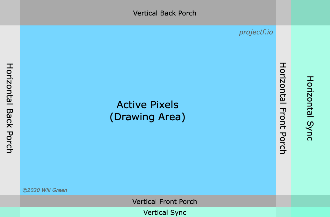
We need 5 signals to drive a VGA monitor.
* R, G and B (red, green and blue signals)
* HS and VS (horizontal and vertical synchronization)
The R, G and B are **analog signals**, while HS and VS are **digital signals**.
{% hint style="info" %}
Signal de (data enable, not shown in picture) is occasionally necessary, but most of the time it is not.
{% endhint %}
### Important parameters
See more at .
| - | 640x480 | 1280x720 |
| ------------------------- | -------- | -------- |
| Horizontal Active Pixels | 640 | 1280 |
| Horizontal Front Porch | 16 | 110 |
| Horizontal Sync Width | 96 | 40 |
| Horizontal Back Porch | 48 | 220 |
| Horizontal Total Blanking | 160 | 370 |
| Horizontal Total Pixels | 800 | 1650 |
| Horizontal Sync Polarity | negative | positive |
| Vertical Active Pixels | 480 | 720 |
| Vertical Front Porch | 10 | 5 |
| Vertical Sync Width | 2 | 5 |
| Vertical Back Porch | 33 | 20 |
| Vertical Total Blanking | 45 | 30 |
| Vertical Total Pixels | 525 | 750 |
| Vertical Sync Polarity | negative | positive |
{% hint style="info" %}
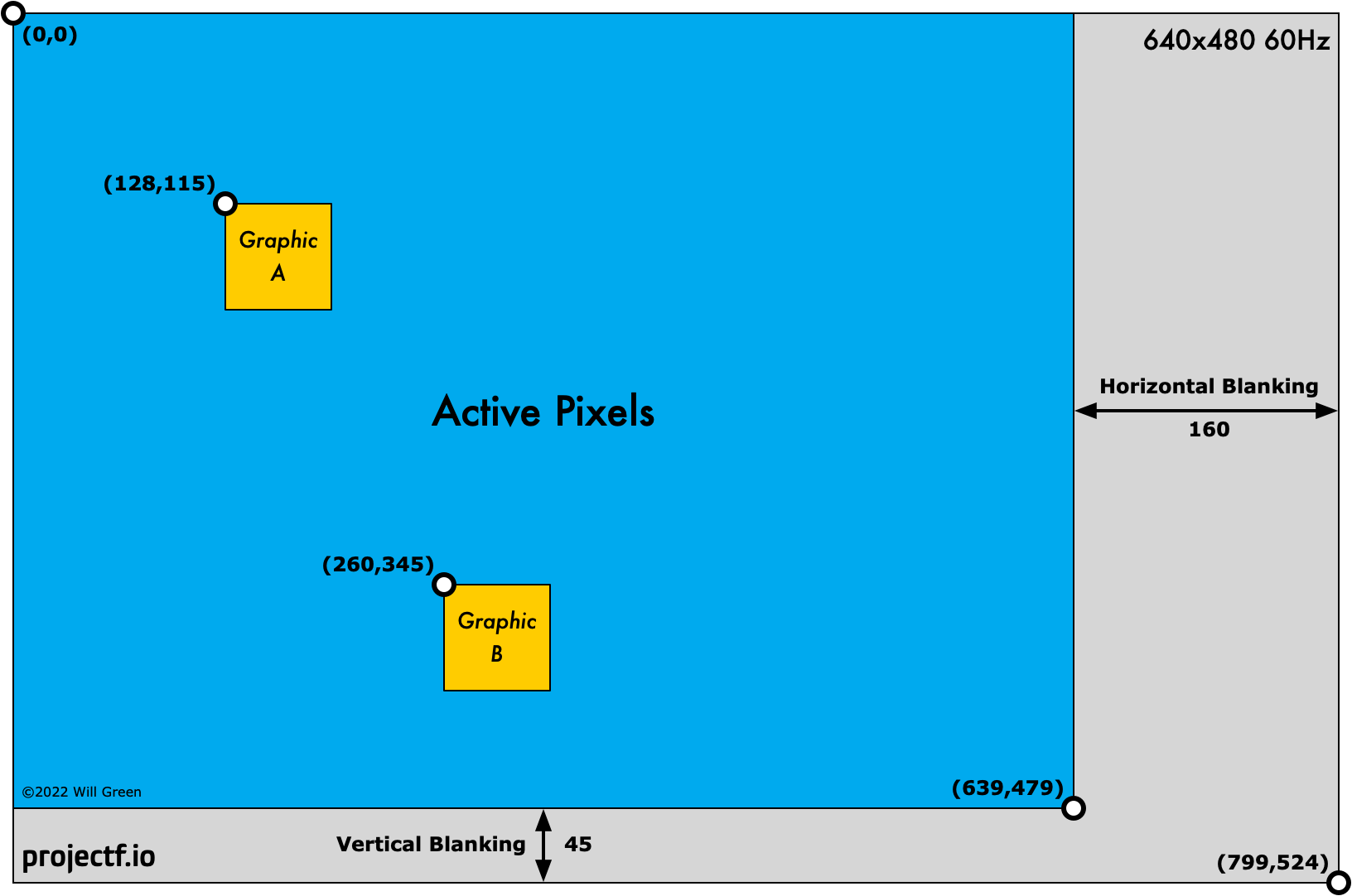
Image a 640x480 @ 60Hz VGA monitor. What's the bandwith of it?
There are 640x480 pixels in one frame, and each pixel cantains 24bit RGB values. So The bandwith should be 640x480x24x60 bps, roughly 0.44Gbps. But remember we have ***off-screen area*** because of the horizontal and vertical blanking intervals (more precisely, ***horizontal and vertical front and back porches, horizontal and vertical synchronization***). Our 640x480 frame is actually sent as an 800x525 frame. So the actual bandwith is roughly 0.6Gbps, but only %73 of it really transfers the data.
{% endhint %}
### Generate VGA signals
{% hint style="info" %}
A important concept is **pixel clock**, i.e., the number of pixels painted per clock. For example, a 640x480 @ 60Hz VGA monitor has pixel clock 800x525x60Hz = 25.2MHz (offscreen area is calculated as well).
{% endhint %}
Because the pixel clock is often different with the system clock, we need a pixel clock generator. We can use counter to do this, but more often we use PLL or MMCM IP cores. If we have pixel clock, then we can build **hsync** and **vsync** signals.
The following exmaple code demonstrate how to generate some of the important signals. (comes from [simple\_480.sv](https://github.com/projf/projf-explore/blob/main/graphics/fpga-graphics/simple_480p.sv))
```verilog
module simple_480p (
input wire logic clk_pix, // pixel clock
input wire logic rst_pix, // reset in pixel clock domain
output logic [9:0] sx, // horizontal screen position
output logic [9:0] sy, // vertical screen position
output logic hsync, // horizontal sync
output logic vsync, // vertical sync
output logic de // data enable (low in blanking interval)
);
// horizontal timings
parameter HA_END = 639; // end of active pixels
parameter HS_STA = HA_END + 16; // sync starts after front porch
parameter HS_END = HS_STA + 96; // sync ends
parameter LINE = 799; // last pixel on line (after back porch)
// vertical timings
parameter VA_END = 479; // end of active pixels
parameter VS_STA = VA_END + 10; // sync starts after front porch
parameter VS_END = VS_STA + 2; // sync ends
parameter SCREEN = 524; // last line on screen (after back porch)
always_comb begin
hsync = ~(sx >= HS_STA && sx < HS_END); // invert: negative polarity
vsync = ~(sy >= VS_STA && sy < VS_END); // invert: negative polarity
de = (sx <= HA_END && sy <= VA_END);
end
// calculate horizontal and vertical screen position
always_ff @(posedge clk_pix) begin
if (sx == LINE) begin // last pixel on line?
sx <= 0;
sy <= (sy == SCREEN) ? 0 : sy + 1; // last line on screen?
end else begin
sx <= sx + 1;
end
if (rst_pix) begin
sx <= 0;
sy <= 0;
end
end
endmodule
```
{% hint style="info" %}
We specify sx and sy as 10 bits registers. You should change it to fit your own needs, otherwise ***it may not show anything***. Try to explain why according to the code. (hint: sx overflow)
{% endhint %}
## Top level design
Four stages:
1. Pixel Clock
2. Display Signals
3. Drawing Graphics
4. Video Output (VGA, HDMI, DisplayPort)
{% hint style="info" %}
Try to answer the following questions, you may have your own answer.
* Why "clk\_pix" points to "Drawing Logic"? Are "sx" and "sy" enough?
* Is the design pattern good? Why?
* Better design patterns?
{% endhint %}
## References
{% embed url="" %}
{% embed url="" %}
{% embed url="" %}
---
# Agent Instructions: Querying This Documentation
If you need additional information that is not directly available in this page, you can query the documentation dynamically by asking a question.
Perform an HTTP GET request on the current page URL with the `ask` query parameter:
```
GET https://byrzhm.gitbook.io/build-a-risc-v-chip-from-scratch/interfaces/graphics/vga.md?ask=
```
The question should be specific, self-contained, and written in natural language.
The response will contain a direct answer to the question and relevant excerpts and sources from the documentation.
Use this mechanism when the answer is not explicitly present in the current page, you need clarification or additional context, or you want to retrieve related documentation sections.